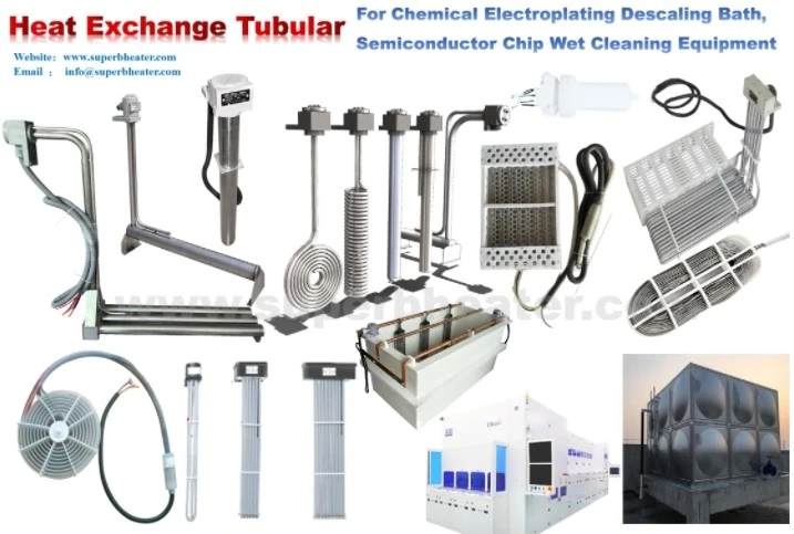
A semiconductor wet bench running SC-1 chemistry at 75°C replaced a 2 kW PTFE immersion heater after just three months. The heater had been mounted vertically in a narrow process tank with minimal clearance on all sides. The failure pattern was distinctive: a band of blistered, discolored PTFE on the sheath surface, matching the location where the tank's circulation flow had been blocked by a wafer cassette support. The watt density was 1.8 W/cm²-well within the range for agitated aqueous baths. The layout was the problem.
Steam blanketing occurs when the heat flux at the sheath surface exceeds the rate at which the surrounding liquid can remove it. A vapor layer forms, insulating the sheath from the fluid. Surface temperature spikes. PTFE softens and degrades. The condition is self-reinforcing-once a vapor blanket forms, heat transfer efficiency collapses, and the sheath temperature climbs until the polymer fails.
Semiconductor wet benches are particularly vulnerable because tank geometries are compact, clearances are tight, and flow paths are obstructed by wafer carriers, cassettes, and process hardware. A heater that would operate safely in an open plating tank may develop steam blanketing in a wet bench where flow around the sheath is restricted.
What Triggers Steam Blanketing at the Sheath Surface
The critical heat flux for water-based process fluids at 70–80°C is roughly 3–5 W/cm² under ideal flow. In practical wet bench conditions, with obstructions and limited clearance, the effective critical heat flux drops to 1.2–2.0 W/cm². Exceeding that threshold initiates vapor formation at the hottest point on the sheath.
Once vapor forms, the local heat transfer coefficient falls by a factor of ten or more. The sheath temperature rises rapidly-often within seconds-to the point where PTFE softens. The vapor blanket expands, spreading to adjacent areas. The heater fails from the outside in, even though the resistance element and MgO insulation remain intact.
| Local Flow Condition | Effective Critical Heat Flux | Safe Watt Density Limit | Steam Blanketing Risk |
|---|---|---|---|
| Unobstructed, >0.3 m/s | 3.0–4.0 W/cm² | 1.8–2.2 W/cm² | Low |
| Moderate clearance, 0.1–0.3 m/s | 2.0–2.8 W/cm² | 1.4–1.7 W/cm² | Moderate |
| Tight clearance, <0.1 m/s | 1.2–1.8 W/cm² | 0.9–1.2 W/cm² | High |
| Blocked flow, near stagnant | <1.0 W/cm² | 0.6–0.8 W/cm² | Very high |
Effective critical heat flux values based on field measurements in semiconductor wet benches with SC-1 and SC-2 chemistries at 70–80°C
Why Compact Wet Bench Layouts Amplify the Problem
Semiconductor wet benches prioritize wafer handling, chemical exposure uniformity, and footprint efficiency. Heater placement is often an afterthought-the unit goes wherever space remains after the process tanks, plumbing, and wafer transfer mechanisms are positioned.
The result is predictable. The heater sits in a corner. A cassette support blocks flow on one side. The clearance between the sheath and the tank wall is 15–20 mm-enough to fit the heater but not enough for meaningful fluid circulation. The local flow velocity at the sheath drops below 0.05 m/s. The boundary layer thickens. The critical heat flux falls. Steam blanketing initiates at the first hot spot.
Field data from wet bench installations shows that sheath temperature differentials of 35–50°C above bulk fluid are common in tight-clearance zones at 1.5 W/cm²-well into the range where vapor formation begins.
Layout Configurations That Maintain Flow Around the Sheath
The layout of the heater within the tank determines whether the fluid can remove heat effectively. Three configurations are common in semiconductor wet benches.
Perimeter-following layout positions the heater along the tank wall, with the heated section running parallel to the wall at a distance of 40–60 mm. This creates a vertical flow channel between the sheath and the wall. Natural convection or a small eductor can drive flow through that channel, maintaining boundary layer renewal along the entire heated length. The clearance must be sufficient for fluid movement but not so large that the flow bypasses the heater.
Distributed multi-pass layout uses several shorter heated sections positioned at different locations around the tank perimeter. Each section operates at lower watt density, and the distributed heat load reduces the peak flux at any single point. This configuration is particularly effective in tanks with complex internal fixturing where a single long heater cannot avoid obstructions.
Central vertical layout positions the heater in the middle of the tank, away from walls and fixturing. This provides the most uniform flow access if the tank is large enough. In compact wet benches, however, a central heater obstructs wafer transfer and is rarely practical.
| Layout Configuration | Flow Access | Watt Density Limit | Best Application | Steam Blanketing Risk |
|---|---|---|---|---|
| Perimeter-following, 40–60 mm clearance | Good, vertical channel | 1.4–1.7 W/cm² | Narrow tanks with wall space | Low–Moderate |
| Distributed multi-pass | Excellent, multiple flow paths | 1.2–1.5 W/cm² | Complex fixturing, tight spaces | Low |
| Central vertical | Excellent, unobstructed | 1.6–2.0 W/cm² | Large tanks only | Low |
| Corner-mounted, tight clearance | Poor, blocked flow | 0.8–1.0 W/cm² | Not recommended | High |
Layout recommendations based on field data from 28 semiconductor wet benches with PTFE immersion heaters
Agitation and Flow Augmentation in Compact Tanks
Passive layout changes alone cannot guarantee adequate flow in every wet bench. Active flow augmentation-using a small eductor, sparge pipe, or recirculation loop-provides a direct means of maintaining flow at the sheath surface.
An eductor nozzle positioned 100–150 mm from the heater, discharging parallel to the heated section, raises local flow velocity to 0.3–0.5 m/s. This reduces the boundary layer thickness and lowers sheath temperature by 15–25°C at the same watt density. In wet benches where space permits, a small pump-driven eductor loop is the most reliable method for preventing steam blanketing.
A dedicated sparge pipe beneath a vertically mounted heater provides a lower-cost alternative. Air bubbles rising along the sheath surface disrupt the boundary layer and promote mixing. The sparge rate required is modest-0.5–1.0 CFM per linear meter of heater length-and the air must be oil-free and filtered to avoid contaminating the process bath.
| Flow Augmentation Method | Local Flow Velocity | Sheath ΔT Reduction | Watt Density Increase | Complexity |
|---|---|---|---|---|
| None (layout only) | 0.05–0.15 m/s | Baseline | - | Low |
| Dedicated sparge pipe | 0.1–0.2 m/s | 8–15°C | +0.2–0.3 W/cm² | Low |
| Eductor nozzle | 0.3–0.5 m/s | 15–25°C | +0.3–0.5 W/cm² | Moderate |
| Recirculation loop | 0.4–0.6 m/s | 20–30°C | +0.4–0.6 W/cm² | Higher |
Flow augmentation data from wet bench trials with SC-1 chemistry at 75°C, baseline watt density 1.4 W/cm²
Practical Specification Steps for Wet Bench Heaters
Begin with the tank geometry and internal fixturing. Identify where the heater can be positioned with at least 40 mm clearance from walls and 80 mm from wafer carriers or cassettes. If no such location exists, a distributed multi-pass configuration is likely required.
Calculate the safe watt density from the actual flow conditions at the proposed heater location-not from the bulk tank agitation. In tight-clearance zones, derate to 1.0–1.2 W/cm². If flow augmentation is added, a moderate increase to 1.4–1.5 W/cm² is acceptable.
Specify the sheath surface area from the required kilowatt output and the derated watt density. A 3 kW duty at 1.0 W/cm² requires 3,000 cm² of sheath surface-achievable with a multi-pass or perimeter-following configuration within typical wet bench dimensions.
Verify that the heater layout does not obstruct wafer transfer or create dead zones where chemical exposure becomes non-uniform. The heater should complement the process flow, not disrupt it.
When Standard Heaters Cannot Fit the Flow Requirements
Semiconductor wet benches with compact footprints and complex internal fixturing often cannot accommodate standard PTFE immersion heaters at the watt densities that prevent steam blanketing. A 4 kW duty at 1.0 W/cm² requires 4,000 cm² of sheath surface-more than a single straight or L-shaped unit provides within the available space.
Custom multi-pass and perimeter-following PTFE immersion heater configurations distribute the heating surface around the tank perimeter, maintaining low watt density while preserving flow access to the sheath. The specification process requires tank dimensions, internal fixturing layout, process chemistry and temperature, agitation conditions, and required kilowatt output. For facilities running multiple wet benches with varying tank geometries and chemistries, this application-specific approach reduces steam blanketing failures and extends heater service life in the most space-constrained process environments.